- A6M2 and A6M3 Secondary Markings
This article is an examination of the various
secondary markings of the A6M2 and A6M3 Zeros made by both Mitsubishi and
Nakajima. While these details are of relatively minor importance, it is hoped
that this article will serve to expand the scope of the markings that could be
found on these aircraft. Unfortunately, as far as the modeler is concerned, many
of the markings described below are not available on the various decal sheets
currently available. While many of these markings were used on all the Zero that
were built up to the end of the war this article limits itself to examine only
the markings known to be applied to the greenish-gray painted A6M2s and A6M3s.
The changes in the appearance of the serial number data stencil applied to the
port rear fuselage of all Zeros will be the topic of a future study.
For the historian concerned with trying to
identify a specific aircraft note should especially be taken of the sub-assembly
data plates described below. The true serial number of an aircraft was only
coincidentally the same as the serial numbers found on the numerous data
plates scattered throughout a single airplane. A number of preserved Zeros have
been assigned incorrect serial numbers due to the misunderstanding of this fact.
This article could not have been written without
the help of a number of people. Acknowledgment and thanks is hereby extended to
Earl Calverley, Jim Long, Jim Lansdale, Katsushi Owaki, Dave Aiken and Dave
Pluth.
Data Plates/Serial Numbers
In the manufacturing process a small metal data
plate was riveted to each sub-assembly. These plates varied in appearance but
generally each carried a serial number that was applicable to that particular
component. As each aircraft moved along the assembly line these components were
added to the airframe. However, the various components were not necessarily
added to an airframe with the same serial number as had been assigned to the
different sub-assemblies. This is quite understandable when one considers
factors such as varying rates of manufacture between different sections of the
plant, the need for remanufacturing substandard parts and the logistical
problems of hunting down a particularly numbered part when all components were
supposed to be interchangeable anyway. Because
of this the serial numbers found on these data plates cannot be used to identify
the true serial number of a particular aircraft. Having said that, it should
also be pointed out that the serial number on a specific data plate often was
very close to the serial number of the parent aircraft as both probably had been
made at relatively the same time in the manufacturing process.
The data plates used by Mitsubishi and Nakajima
were different in appearance. Mitsubishi plates were rectangular, usually
measuring about 35mm by 75mm. They typically included the Zero type, the
part’s serial number, the date and the inspector’s stamp. Nakajima plates
were larger, either 50mm by 70mm or 55mm by 70mm. They listed the manufacturer,
the Zero type, the aircraft serial number (invariably left blank this line
appears to have been deleted in the late fall of 1942), the part number, the
part’s weight, the inspector’s stamp, the date (this line was ordered to be
left blank as of November 1942 and a number of plates already stamped with a
date subsequently had this line mutilated) and the part’s serial number.
Subcontractors used plates similar, but not necessarily identical, to the plates
used by company they were making parts for.
The actual aircraft serial number was the one
found in the data block painted onto the port side of the fuselage. As the
sub-assembly data plates on each aircraft would invariably have a number of
different serial numbers, the painted fuselage serial number was also painted
close to most, if not all, of the externally visible data plates. Mitsubishi
adopted a pattern with each serial number in one line measuring 32mm by 177mm.
In contrast, the serial numbers painted onto Nakajima built Zeros were in two
lines, the top one measuring 25mm by 88 mm and the lower line 25mm by 120mm in
size. Any removable panel was also painted with the serial number of the parent
airplane on the interior of the component.
|

|
|
Photo 1:
Mitsubishi data plates from the ailerons of several of the A6M3s
captured at Buna in early 1943. Note the difference between the aircraft
serial numbers and the sub-assembly serial numbers. Note also that these
plates were originally made with the expectation that they would be
affixed to an A6M2 Type 21 aileron. (South West Pacific Directorate of
Intelligence, Comments No. 43 on
Captured Documents, Appendix A) |
On the Zero’s exterior data plates and their
accompanying painted serial numbers were found in the following locations:
Starboard Rudder - This plate was affixed just
above second lowest rib of the rudder with the aircraft serial number painted
below the plate. (Model Art 510, p.
81; Hata and Izawa, Japanese
Naval Aces and Fighter Units in World War II, p. 162)
Elevators - In this case the plate was located on
the lower side of each elevator just outboard of the second rib. The airplane
serial number was to the rear of the plate.
|

|
|
Photo 2: Data plate and aircraft
serial number from the underside of the port elevator of A6M3 s/n 3322.
(Photo courtesy of James Long) |
Horizontal Stabilizers
- The plate was located on the underside of each horizontal stabilizer
between the fuselage and rib number 2. The aircraft serial number was to the
rear of the plate at right angles to the fuselage. This plate has been
misinterpreted in many drawings as an inspection access cover. (Model
Art 272, p. 58; Thorpe, Japanese Naval Air Force Camouflage and Markings World War II, p.
101)
|

|
| Photo 3: Data plate and aircraft serial number
from the underside of the horizontal stabilizer of Nakajima built A6M2 s/n 9816.
The sub-assembly number is 6012 and the sub-assembly serial number is 8823.
(Photo courtesy of James Lansdale) |
Ailerons - This data plate, on the underside of
each aileron, was situated inboard of the aileron rib found at the attachment
point of the inboard hinge. The aircraft serial number was painted behind the
plate. (Mikesh, Zero, p. 111)
Landing Gear Covers - The manufacturer’s data
plate was affixed to the center strut attaching the middle landing gear cover to
the landing gear strut. As these covers were not handed the plate could be
located on either the back or front of the cover. (Aero
Detail 7, p. 30, photo 140) The airplane serial number to go along with this
data plate appears to have been painted on the inner side of the lower landing
gear cover. These lower covers were also indicated as being for the right or
left landing gear. ( Model Art 510, p.
180)
|

|
| Photo 4: Landing
gear cover data plate from the subcontractor
Kayaba Seisakujo K. K. The
number 639 is probably an uncoded one, meaning that this was the 639th component
of its kind produced by the company. The
Kayaba company is listed in the United States Strategic Bombing Survey as having
been a supplier of landing gear to the Nakajima company. Note that the date in
the bottom line has been removed. |
Landing Gear Struts - According to Jim Long
research indicates that landing gear struts were made as a pair and bore the
same serial number. Nakajima plates, measuring 45mm by 50mm, were made of brass
and brazed onto the front of the strut. (Model Art 272, p.45) No Mitsubishi plates have yet been located at
the time this article was written.
If an aircraft serial number other than the one on the lower landing gear cover
existed evidence of it has not yet been located. Some landing gear struts had a
metal plate strapped to the front of the strut with two bands that encircled the
leg. The plate carried service
instructions for maintaining the air and oil levels of the oleos. (Model
Art 272, p. 46; Aero Detail
7, p. 63)
|

|
| Photo 5: The
locations of the landing gear strut data plates are shown by the outlines left
when the plates were removed. |
Flaps - Each flap had a data plate on the interior
of the flap skin just inboard of the second flap rib and to the front of the
flap’s central stringer. While one photo (Pat Robinson, The
Fight for New Guinea, General Douglas MacArthur’s First Offensive, picture
of Lt. Col. Edwin Schmidt) has been found that may indicate the location of a
painted serial number below the plate the quality of the photo precludes certain
identification.
|

|
| Photo 6: The
location of the flap data plates are shown by the outlines left when the plate
was removed. |
Drop Tank - Wartime intelligence reports indicate
that each tank also had a data plate but the location is unknown but it may have
been on the fairing between the tank and fuselage. In all likelihood an aircraft
serial number was not painted on the tank but it has been recorded that the last
two digits of the airplane tail code were written on the aforementioned fairing.
Centerline Jig Alignment Markings
These markings, in the shape of red
“crosshairs”, were located on both the fuselage and on the leading edge of
the wings of Mitsubishi Zeros. The latter markings were placed on the leading
edge of each wing at ribs number 16 and 23. (Mikesh, Zero, p. 71) The fuselage markings were found on the centerline just
in front of the horizontal stabilizer, on the front and back edge of the center
section of the fuselage, and on the center fuselage section even with the line
of the front wing spar. (Model Art 510,
pp. 178-179, Mikesh, Zero, p. 113)
While Nakajima built A6Ms might have had similar
markings no evidence to support such a claim has been located. Furthermore,
there is a possible explanation of why only Mitsubishi chose to add these
markings. Mitsubishi transported all of their Zeros from the factory at Nagoya
to the airfield at Kagamigahara on carts with one cart carrying the wings and
center section of the fuselage and a second cart moving the rear of the fuselage
and the engine. Final assembly was then completed at Kagamigahara. It can be
hypothesized that the markings were added to aid in this final assembly process.
Center of Gravity Markings
The port side of the fuselage also carried red and
black markings to delineate the parameters of the center of gravity. These
markings consisted of a red line, accompanied by explanatory lettering in red,
indicating the center line of the fuselage. The front and rear limits of the
center of gravity were shown by two
black crosses with explanatory lettering again in red. The color of these
markings comes from Jim Lansdale’s analysis of the photographs taken of the
Mitsubishi A6M2, s/n 4593, captured
in the Aleutians in 1942. While similar markings have been found on other IJN
aircraft (Model Art 510, pp. 228 and
237 shows such markings on a Rex and a George) it is not completely certain that
Nakajima applied such marking to the Zeros they built. (Model
Art 510, pp. 178-179, Mikesh, Zero,
p. 113)
|

|
|
Photo 7: Fuselage center line
and center of gravity markings from the A6M2 s/n 4593 found intact in
the Aleutians in 1942. (Photo courtesy of James Lansdale) |
Fuel Tank Inlet Covers
The Type 21 and 32 Zeros had one tank in each wing
and one tank in the front of the fuselage. Most sources indicate that the wing
covers on Mitsubishi Zeros were painted red but photos of the Aleutian A6M2 show
that the fuselage tank cover was also red. (Model
Art 272, p.43) It is very likely the inlet covers of the two additional
outboard wing tanks of the model 22 were also red but no photographic evidence
of this has been located. While Nakajima built A6Ms very probably also had their
fuel tank inlet covers painted red no photographic evidence has yet been found.
It should be pointed out that the two round access covers on the upper
side of the wing just inboard of the cannon bay covers were not tank inlet
covers. These panels were there to allow light into the ammunition bays while
the bay was accessed from under the wing. These covers were not red in color.
Hinomaru
A6M2s built by Nakajima can generally be
distinguished by the addition of a white surround to the fuselage hinumaru.
However, it should be noted that this feature was only introduced in the summer
(July?) of 1942. Thus the first 148+ Nakajima built Zeros are rather less easily
differentiated from those built by Mitsubishi.
Weight Indication Markings
Both Mitsubishi and Nakajima painted stripes on
the outer side of the center landing gear strut cover. As weight was added to an
airplane the compression of the oleos caused these markings to be progressively
covered up. Mitsubishi painted three of these stripes, red, yellow and blue from
top to bottom, while Nakajima only applied two of them, a red stripe painted on
top of a blue stripe of double the width. (Model
Art 272, p. 44; Model Art 510,
p. 8)
Trestle Here Markings
These markings were applied to each side of the
rear of the fuselage. The Kana characters for “Trestle Here” (Ko Ko No Se Ru)
were vertically stenciled in red above a black arrow. (Model Art 272, p.
44)
Hokoku Markings
No direct evidence has come to the fore that links
the two styles of Hokoku markings to the two manufacturers of the Zero. However,
Jim Long argues very convincingly that these markings were applied by the
factory and thus can be attributed to either Mitsubishi or Nakajima. He states
that the photos of the A6M3s captured at Buna (FAOW
56, pp. 22-24) show that in this case the fuselage serial number data block
stencils were applied in a different position from the norm in order to
accommodate the rather large and spread-out Hokoku numbers. Long thinks it to be
highly unlikely that some depot painters went to the trouble to blot out the old
stencil, cut a new stencil, and reapply the identification marking in a new
position so that the Hokoku markings could be applied. As it is known that the
factory applied the fuselage data stencils it would appear that the factory also
applied the presentation markings. Furthermore what better way to shorten the
time and effort spent on these presentation markings and events than to have the
manufacturer apply these markings at the end of the production process and then
carry out a lip-service ceremony to thank the people or organization for the
gift.
If Long’s assessment is correct then the Hokoku
numbers in the style seen on the Buna aircraft can clearly be attributed to
Mitsubishi. The other less common pattern (Aero Detail 7, p.44) is therefore that found on Nakajima built
Zeros.
No Step/No Push/Step Here Markings
Both Mitsubishi and Nakajima utilized red Kana
“No Step” (No Ru Na) markings on the upper surface trailing edge of the
wings of the Zeros they built. Mitsubishi also included the characters for “No
Push” (O Su Na) outboard of the “No Step” marking. (Model
Art 510, p. 179) Both manufacturers outlined the no step area with red
lines, but Mitsubishi (no details are available as to Nakajima's practice) left
the outboard side of the rectangle outline unpainted. In contrast the “Step Here” indicator set inside a
stenciled oval, which was only found on Mitsubishi A6Ms, was applied in black.
Aileron Weight Markings
The Mitsubishi Zero Handling Manual in the collection of Blayd (a later
edition than that reprinted in Model Art
323) stipulates that ailerons with mass balance arms should be stenciled in
red with the three characters for “with arm” on the outer end of the upper
surface. The mass balance arm was fitted, either during production or as a
retrofit, to the first 326 Zeros built by Mitsubishi. Ailerons with the heavier
internal mass balance weights (starting with Zero number 327) were in turn to be
marked in red with the four characters for “increased weight” in a similar
location. Presumably these markings applied only to the Type 21 Zero and
possibly only to Mitsubishi made airplanes of this type.
|

|
|
Photo 8: Japanese characters
for “No Step” “No Push” “Increased Weight” (left
to right, upper line) “With Arm” (lower line)..
|
Latch Release Markings
These round black dots, ½ inch in diameter, were
located on the front half of the latch for the four small oval mid-fuselage
access panels (two per side) and the outer facing half of the latch for the
folding wingtip release access panel. (Sakaida, Imperial
Japanese Navy Aces 1937-45, p. 19) As well, at least one photo also
indicates that similar dots were placed on the release buttons for the spring
loaded handholds and steps on the port side of the fuselage. (Sterling
Collection, http://24.237.4.114/Japan/jap-004.jpg) The location of the bottom
step which retracted into the rear of the wing root was indicated by a black
arrow. (Model Art 272, p. 44; Rearden,
Koga’s Zero, p. 67)
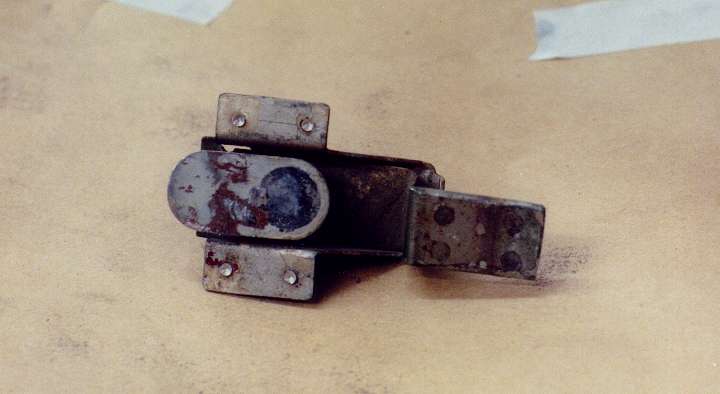 |
|
Photo 9: Black Dot on a latch
release |