A6M1 Drawings
Evidence and Theory Presented by Jim Long
Part Two
The June 1974 issue of the Koku-Fan Monthly published four more pages of technical drawings in the series on the Zero. Three of the pages have drawings that seem to be associated with the two A6M1s. Two pages of material concern the cockpit equipment and one page has to do with the hydraulic system.
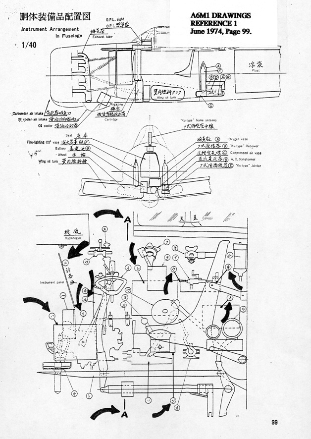
Consider the cockpit equipment first by looking at the lower diagram on page 99 and the two diagrams on page 100, the three of which present a side view, a pilot's forward view, and a pilot's mirror view of a Zero's cockpit. One would assume that the views represent the layout of an A6M2 cockpit, because most of the drawings in the series are associated with that second model. But close examination of the arrangement of equipment and the shape of the instrument panel make it clear that these three diagrams show a cockpit that is different from those in any of the well-known models of the Zero. I believe these drawings illustrate the cockpit layout of the two A6M1s. I'll tell you why I think so.


First lets get the layout oriented. The equipment and fittings in the cockpit, as seen from the left side in the diagram on page 99, are called out by Kana characters in circles which also appear for identification purposes on the other two drawings on page 100. For example, note that the instrument panel is labeled ni by the small symbol in a circle, the one with a short horizontal line over a longer horizontal line, the same symbol that stands for the word "two." That very same symbol appears on page 100 to identify the instrument panel. The upper drawing on page 100 is a pilot's view from Section A-A, as marked on the drawing on page 99, as he looks toward the front of the aircraft. The lower drawing has an mirror-image arrangement, in that it is a view that looks aft from Section A-A, as if the pilot were looking over his shoulders through a mirror at the things beside and behind him. And the relative fore-and-aft positions of the various pieces of equipment are indicated by solid lines and invisible (dashed) lines in this opposite or backward view. Thus, it can be interpreted from observing the solid and dashed lines on the pilot's right that the radio transmitter (re) is forward of the two controls (u and wi) associated with the Ku-Type radio direction finding equipment and is also forward of the mouthpiece case (no).
Now have another look at the instrument panel (ni) in the upper diagram on page 100. It has a shape completely different from any other Zero model. No A6M2, A6M3, A6M5, or any other A6M that we know well ever had a panel like that. It is wider and has more area, with different cutouts and mounting fixtures. So what are these diagrams doing in a set of drawings about the Zero? It is because they do show the cockpit arrangement of a Zero, but not the Zero we supposed - not the A6M2. It is my theory that these drawings are of the A6M1 cockpit layout. That is just about all they could be, because they show such a unique arrangement, an arrangement that we can't associate with any other model of the Zero. It has got the be the A6M1. We just haven't recognized it until now. The original drawings with the original legends are no help because they only identify the aircraft as the Zero Fighter in Japanese characters, Reisen, then label the subject and specify a drawing scale. Examples of the original legends can be seen on pages 8-9, 12-13, and 16-17 of an old 1974 book called "Japanese Navy Wings of the Second World War," Bunrindo Co., Ltd., Tokyo, February 1974. This book was No. 47 in the original FAOW series of books.
If you will study the attached diagrams carefully, you will notice that some of the cockpit facilities are in places different from the A6M2. The radio receiver (ha) is located low on the floor near the pilot's left foot. This is a place taken by the electrical distribution switch panel and a small horizontally arranged auxiliary instrument board holding fuel-quantity and air-temperature gauges in the A6M2. But in this diagram of what I'm convinced is the A6M1 cockpit layout the electrical distribution panel (tsu) is on the right, below the radio transmitter. Look for it on page 100 at the lower right of the lower diagram. It seems that these two items, the radio receiver and the distribution panel, were relocated in the A6M2. In the A6M2 the electrical distribution switch panel is in a higher location on the pilot's left, and the radio receiver was moved to the right side in front of the transmitter. And these drawings also indicate that the A6M1 did not have the horizontal instrument board with fuel-quantity and air-temperature meters on it. Perhaps these items were mounted on the main instrument panel in the A6M1.
Another thing, the irregular-shaped unit with the handle marked ri in the diagram on page 99 is not on any A6M2. The diagram on page 99 and the upper diagram on page 100 show that it is at the lower right front of the cockpit, a place where the radio receiver is located in the A6M2. It is a rather large piece of equipment, and
it has pipes connected to it, meaning that it is either part of the fuel system or part of the hydraulic system. I haven't been able to translate the Japanese label completely, but the diagram on page 100 designates it in English as a starter, which isn't a lot of help, except that that term is used elsewhere in the drawings of hydraulic-system components. I believe it is a hydraulic pump and regulator, a component of the hydraulic system that actuates the landing gear operations and interconnects with the flap controls.
Also, the item marked ru in the diagram on page 99 and further identified in English as a heat insulator in the upper diagram on page 100 is not on any A6M2 or later aircraft. A translation of the Japanese label may reveal something more, but at present I don't know the purpose of this cylindrical object. But I do know that it is not on an A6M2, and this is further evidence to support my theory.
One more thing; notice the shape of the control stick. It is curved like a crane's neck and has a hand-fitting shaped handle. It was probably unique to the prototype A6M1, for in the drawing of A6M1 controls (Part One), the stick is like that of an A6M2. This suggests that the second A6M1 received a modified stick, which may have been retrofitted to the prototype, as well.
For some reason, writer and artist Shigeru Nohara omitted these three drawings from his Green Arrow book entitled "Illustrated Zero Fighter." Perhaps by the time of its publication, 1995, Nohara had come to doubt the material and was wondering why it was so different from the cockpit of an A6M2. Perhaps he dropped the material because he didn't know what it was. But earlier, in his Model Art Publication No. 323 of 1988, he did include the three drawings. The trio of graphics appear on pages 91 and 92 as material inserted by Nohara in a reprint of an authentic A6M2 handling manual.
You don't have to have the Koku-Fan Monthly or Model Art Publication No. 323 or "Japanese Navy Wings of the Second World War" to get a firsthand look at the three drawings I've been telling you about. They also appeared in FAOW No. 5/1987-7. Perhaps you have that booklet in your library. They are on page 43. And there is a diagram of an A6M2 instrument panel on the same page for comparison. The legend above the drawings identifies the material as cockpit equipment placement diagrams and in parentheses lists the source as the Air Technical Arsenal, as traced by Shigeru Nohara.
All of this evidence tells me that these three drawings show the cockpit of the two A6M1s. If you'll study the drawings and compare them to the A6M2 and other later models of the Zero, you may come to the same conclusion. Apparently these drawings of the A6M1 cockpit arrangement were in the Zero files of the Naval Air Technical Arsenal for historical purposes, since the two rather unique A6M1s were not operational planes and one had even been lost in the testing program. Shigeru Nohara, who seems to have been the person who discovered the file and brought it to light, apparently didn't realize what he had and merely published the material along with A6M2 drawings without comment.
Now turn your attention to page 101 in the Koku-fan Monthly for June 1974. The six diagrams on the page detail the Zero's hydraulic system, called oil pressure system on the drawings. The material for the most part illustrates the hydraulics of the A6M2. But one of the drawings is of the A6M1, for the diagram of the tail wheel oleo shows that it was mounted on the 15th fuselage bulkhead. The presence of only 15 formers screams A6M1 out loud. As explained in Part One, the A6M1 was shorter than the A6M2 by a factor of one fuselage former. Therefore, at least the drawing of the tail wheel oleo does show the configuration of the A6M1.
If you have the Green Arrow book, you can see Nohara's tracings of three of the six drawings that show the hydraulic system. They are on page 98 and include the drawing of the A6M1 tail wheel oleo.
References
(Note: Only new references are listed below. See earlier parts for lists of other references that are mentioned in Part Two.).
5. Model Art Co., Ltd. Publication No. 323, "Type Zero Carrier Fighter Models 11/21."
Compiled by Shigeru Nohara, Tokyo, 1988. This book prints an authentic handling manual for the A6M2, applicable to A6Ms No. 6 and after. The basic handling manual is dated 7 July 1940 and was published by Naval Air Headquarters and compiled by Mitsubishi Heavy Industries, Ltd. Shigaru Nohara has added some material of his own in front of the manual reprint: 34 pages of photos, drawings, and text. The reprint begins on page 35 and occupies the remainder of the book's 166 pages. Nohara has intermingled some photos and some diagrams from other sources in with the diagrams from the authentic handling manual. The photos include some from World War II Allied intelligence documents. But all of the drawings are from the Naval Air Headquarters handling manual or from the Zero Fighter Structural Drawings from the Air Technical Arsenal, as reprinted by Koku-Fan Monthly in 1974. Whenever one of the drawings from the Air Technical Arsenal is inserted in the Mitsubishi handling manual, the fact is pointed out to the reader by a note in brackets: [N.A.].
6. Famous Airplanes of the World No. 5/1987-7, "Type Zero Carrier Fighter Model 11-21," Bunrindo Co., Ltd., Tokyo, 1987. Pages 38 through 45 print some authentic drawings, all supposedly of A6M2 features. But page 43 has the cockpit drawings mentioned above.
7. Famous Airplanes of the World No. 47, "Japanese Navy Wings of the Second World War," Bunrindo Co., Ltd., 1974. The three drawings of the Zero cockpit are reproduced on page 17.