
A6M1 Drawings
Evidence and Theory Presented by Jim Long
Part Six
The Conclusion
With such a number of authentic diagrams of the A6M1 available, as has been demonstrated in the five previous parts of this report, this question must be asked: has an accurate depiction of the first A6Ms ever been produced? The answer is that no artist or draftsman has yet done it.
Two artists in Japan have come the closest to drawing accurate profiles. These men are Shigeru Nohara and Rikyu Watanabe. Both artists have had successes early in the 1980s. Before those times, profiles of A6M1s were nothing more than adaptations of A6M2s, all with the addition of external air scoops, some with external mass balances on their ailerons, some with external mass balances on the elevators, of all things, and none with shortened fuselages and the broad and pointed vertical tails
Watanabe had a good profile of an A6M1 in
1980. It was published in "Zero Fighter" by Mikesh and Watanabe.
Watanabe's profile would have been just about perfect if he had omitted the
external carburetor air scoop. In that configuration, his drawing would have
represented the prototype A6M1 as originally built before flight testing and
before the small fin recommended by the navy was added to improve spin recovery.
If Watanabe had illustrated an aerodynamic balance piece forward of the hinge at
the top of the rudder and the small fin, his drawing would then have represented
the No. 2 A6M1 during flight testing just before it crashed in March 1940. It is
obvious that Watanabe based his drawing upon the profile that helped to
illustrate the antenna system of the first six A6Ms (Koku-Fan Monthly for
November 1974, page 188). Further, it is very likely that he referred to the
photograph showing an A6M1 suspended from a hoist in a crowded hangar, one of
the few images we have of an early plane in a
paint finish. This photo has appeared in many books, including Mikesh's
"Zero: Japan's Legendary Fighter," page 21. This particular photo has
invariably been captioned as showing the No. 2 A6M1 undergoing vibration tests,
but a few researchers suspect that it might have been the unnumbered airframe
that was subjected to nonflying tests of vibration and strength, as reported by
Jiro Horikoshi on page 59 of his book "Eagles of Mitsubishi."
Nohara is to be commended for his several efforts to illustrate the A6M1. The earliest one I know of was the profile in Squadron/Signal's issue on the Zero: "A6M Zero in Action." It shows more detail, but is essentially like Watanabe's, except that the vertical tail is not quite right in shape. The curves of the tip aren't correct. And, of course, the external intake air scoop is present. There is no small spin-recovery fin and no balanced rudder, therefore, it must be a representation of the first flying A6M1 before the commencement of flight testing.
Another of Nohara's early interpretations appeared in FAOW No.5/1987-7, page 15. But this drawing, like Watanabe's and Nohara's own earlier attempt, suffers from the presence of an external air scoop for the engine intake and, what is more, the presence of a long oil cooler air scoop under the engine cowling, the latter probably having been taken from that controversial drawing of an A6M1 that was published in Jiro Horikoshi's "Eagles of Mitsubishi" in Japanese in 1970 and in English in 1981. In the English-language version, the drawing is on page 43, billed as the "basic shape of the Prototype 12."
The profile in Eagles of Mitsubishi is the one drawing that has probably been responsible for the persistence of the external air scoop, even though the authentic drawings printed in the Koku-Fan Monthly show that idea to be false. In some form or another, it has undoubtedly been around for a long time, long enough to influence the drawings of the 1960s, and maybe even the 1950s. You would think that a drawing of an A6M1 appearing in a book by the designer would be accurate, wouldn't you? And it may be accurate, but only in showing Horikoshi's original concept, for it is now painfully obvious that the great designer's fundamental ideas were revised as the process of creating the first A6M1 went forward. Horikoshi may have envisioned an external carburetor air scoop when the preliminary drawings of the proposed 12-Experimental Carrier-Based Fighter (the A6M) were being put forth in 1937/38, but by 1939 the latest thinking on engine accessories had taken effect and the air scoop went under the cowling. It is clear that Horikoshi was not alone in designing the A6M. It was a team effort, and the recommendations of the staff of the design group that handled propulsion must have had influence over the final configuration. Hirokoshi's own book names six men who formed the propulsion group, headed by a man named Den-ichiro Inoue. The Inoue group must have had a lot to say about how the Zuisei 13 was mounted, housed, cooled, and fed.
Yet another of Nohara's drawings of an A6M1 accompanied the material added at the front of the handling-manual reprint in Model Art Publication No. 323. It appears on page 4 of the book.
Although it is a good effort and shows detail, it seems to suffer from a shallow fuselage tail cone. It looks too small for the rest of the plane.
Nohara's latest drawing of an A6M1 is in FAOW No. 55/1995-11, page 82, in the Green Arrow book, page 8, and in Aero Detail No. 7. It is by-and-large the same drawing that appeared in the Model Art book, except that it has been revised to show a shallow oil-cooler air scoop like the one seen in the WWII technical drawing on page 143 (diagram 169) of the Model Art book.
I suppose that the next step in the evolution
of the A6M1 would be for one of the men named above, or someone else with an
authoritative standing among us, to draw up and publish a new version of the
A6M1 based upon the well-known photos of A6M1s and upon the drawings identified
in this report that were printed by Koku-Fan in 1974 and by Model Art in 1988.
Until that happens, you cannot make a model of an A6M1 without an external air
scoop and with an aerodynamic balance on its rudder and expect to win a contest
with it. Such a model will not be accepted by the judges until an authoritative
reference can be cited.
As I pointed out in the introduction, it will be necessary to decide on which of several A6M1 configurations you wish to model or illustrate. Here are the two configurations I came up with:
1. A6M1 No. 1 (serial number 201), as built in the experimental shop, before completion and before flight testing. Date would have been around March 1939. This plane had an unbalanced rudder, i.e., one with a straight leading edge and no aerodynamic balance area; this fact has been proved conclusively by clear photos published for the first time in Japan in September 2001. The plane's horizontal tail was placed at the fuselage reference line and had a slight negative angle of incidence. Other configurations pointed out in this paper also apply, such as the position of the aileron/flap junction, the length of the fuselage aft section, and the absence of an external carburetor air scoop if the authentic drawings from the files of the Air Technical Arsenal are to be believed. If the plane is to be shown or modeled as it would have appeared during early flight testing, a small fin must be added to the fuselage. A few artists have attempted to illustrate this fin, but it seems likely that they are artistic impressions and that no one really knows what the fin was like or exactly where it was placed. If this plane were still being flown after the trouble with the aileron balance was discovered and remedied in May 1941, it would have had the external mass-balance arm applied to its ailerons as a retrofit. This feature could be included in an illustration or on a model that was representing the latest configuration.
2. A6M1 No. 2 (serial number 302), as configured at the time of its crash in March 1940. This plane may have started life with the straight-edged rudder of the prototype, but it was modified during testing to have a rudder that was aerodynamically balanced. The obvious implication has to do with creating lighter control forces. Probably designers and test pilots discovered by test flying the prototype and perhaps this second A6M1 that the rudder bar forces became too great at high speeds. The purpose of the balance area of a rudder is to reduce the hinge moment necessary to move the control surface. The photo evidence shows that such an aerodynamically balanced rudder was applied to the second A6M1 at some time before its crash. And the same facility was made a standard part of the design beginning with the first A6M2 (serial number 403). A6M1 No. 2 never had the external balance weights on its ailerons, since the plane crashed before that problem emerged.
If we knew more about the history of the testing
of the individual A6M1s, we could undoubtedly come up with a few other
configurations and dates. But with the information presently available, the two
variations listed above are the only ones with credible support. Many questions
are left unanswered, and the quest for answers will no doubt go on for a long
time. In closing this report, I acknowledge the help given me by friends and
associates with sincere thanks: Dave Pluth, Rob Graham, Hiroyuki Takeuchi, and
Jim Lansdale.
a. Reference 5, page 130, diagram 150 (showing the 7.7mm cowl guns with both the A6M1 and A6M2 installations on the same drawing).
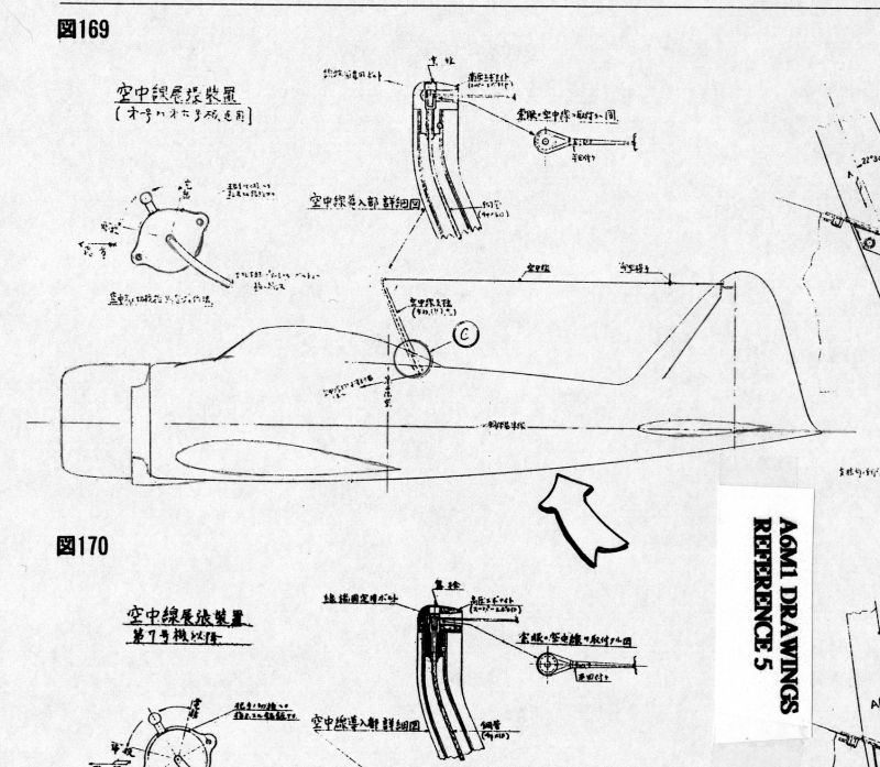
b. Reference 5, page 143, diagrams 169 and 170 (showing profiles of the A6M1 and the A6M2 in illustrating the antenna system).

c. Reference 5, page 151, diagram 184 (showing dimensions of assemblies) [the last 1 of page 151 was probably lost from your hard copy of the page; it appears as 15 in the lower right corner].

Reference 8, page 38 [not marked on page] (showing the carburetor air scoop on the F1M2 Pete)
Jim Long
Ocean Springs, Mississippi, August 2001
References
10. Zero Fighter, text by Robert C. Mikesh, Illustrations by Rikyu Watanabe, Zokeisha Publications, Ltd., Tokyo and New York, 1980. Page 33 has the very good drawing of an A6M1, except for the two objectionable items mentioned in the text above.
11. Squadron/Signal Publications, Aircraft Number 59, A6M Zero in Action, by Shigaru Nohara, illustrated by Don Greer & Shigaru Nohara, Carrollton, Texas, 1983. The A6M1 is on page 5. It was drawn with complete rivet detail, but much has been lost in a printing of reduced size.
12. Jiro Horikoshi, Eagles of Mitsubishi: The story of the Zero Fighter, translated by Shojiro Shindo and Harold N. Wantiez, University of Washington Press, 1981. Originally published in Japanese in 1970 by Kappa Books (Kobunsha Co.), Ltd., Tokyo, Japan. Page 43 has three views of the "basic shape of the Prototype 12." About the only things that look like the familiar Zero are the plan view and the front view. The profile gives a distorted view, with a cockpit enclosure that seems too big and too far aft and a vertical tail that looks too small. The external air scoop is present, as is a long oil-cooler air scoop at the bottom of the cowling. The landing gear legs are angled forward too much. There are photos sandwiched between pages 96 and 97 that show some blueprints and a wooden model the prototype A6M1. These items confirm that Horikoshi dreamed of a cockpit that was farther aft. They also show that there had been some miscalculations about the area needed for the vertical tail: the photos of the blueprints and one of the photos of the model indicate that some tinkering with the size and shape of the vertical tail went on. Where are those blueprints today? The photo shows that there were some eight or nine bindings of blueprints on the A6M1. It would be wonderful to find them. They would probably answer a lot of questions.
13. Maru Magazine, Special Issue No. 6, Zero Photo Album, April 1963. This small booklet is one of the earliest publications I have. It has a drawing of an A6M1 that looks just like an A6M2, but with an external air scoop, a three-bladed prop, an external mass balance arm on the elevator, and a rudder with an aerodynamic balance surface forward of the hinge line.
14. Famous Airplanes of the World No. 10, Type Zero Carrier-Based Fighter, Models 11-22, Bunrindo Co., Ltd., Tokyo, 1974. Page 43 has a line drawing just like the rendering that appeared in Maru Magazine's Special Issue No. 6 (Reference No. 13, above).
15. Encyclopedia of Japanese Aircraft 1900-1945, Volume 1, Mitsubishi's Aircraft, Shuppan-Kyodo Publishers, Tokyo, 1966. This volume, part of a set of eight volumes, is an old and respected publication. It was first published in December 1958, revised in April 1961, revised again in November 1962, yet again in March 1966, and finally revised and reprinted for the last time in May 1981. But it is not without flaws. And the inaccurate external air scoop on drawings of the A6M1s may possibly be traceable to this volume. It might prove to have been the original culprit if it can be shown that the 1958/61/62 editions carried the same drawing of an A6M1 as the 1966 edition did.
The 1966 and the 1981 volumes have similar drawings of an A6M1 by Katsusuke Komuro. They are both basically pictures of an A6M2, altered to fit what was thought to be the image of the A6M1. The version for 1981 was updated slightly to have a larger oil-cooler housing, to have a straight-edged rudder, and to move the exhaust-pipe outlets up to the fourth cowl flaps. These 1966 and 1981 drawings both have external carburetor air scoops, and they both have external mass balance arms on their elevators.
16. Profile Publications Number 29, The Mitsubishi A6M2 Zero-Sen, by Ren‚ J. Francillon. Profile Publications Ltd., Surrey, England, No Date. This little booklet of the 1960s has color drawings of A6M1 Nos. 1 and 2. The planes are really A6M2s with external air scoops atop the cowling and the air scoop of the A6M2 removed.
17. Sankei Publishing Co., Second World War Books, Volume 68, Zero Fighters, by Etsutaro Tanaka, Japan, 1976, ISBN4-383-01465-8. This small book has a profile of an A6M1 on page 83, but it is just an A6M2 modified to show an external carburetor air scoop on the top of the cowling and the deletion of the A6M2's air scoop at the bottom.
18. Aero Detail No. 7, Mitsubishi A6M Zero Fighter, by Shigeru Nohara. Dai Nippon Kaiga Co., Ltd., Tokyo, 1993. Page 70 has the A6M1 and some text which says that the rear fuselage was slimmer and the tail aft of former 11 was shorter. But these factors do not show up in the authentic WWII profiles. If measurements are made of the profiles on page 188 of the November 1974 Koku-Fan and on page 143 of Reference No. 5, you will see that the fuselage of the A6M1 and the A6M2 are the same size out to former 12 and that the A6M1's fuselage is only slightly more shallow below the reference line aft of that point.
19. Maru Magazine Editorial Section, "Maru Extra - Senshi to
Tabi #30, September Special Issue," Japanese magazine code 08308-9,
published in September 2001 by Kojinsha, Tokyo, Japan. This special issue from
Maru Magazine has published newly discovered photos of an A6M1 being
constructed. Presumably it shows the prototype being built in Mitsubishi's
experimental shop.